
TECHNICAL OVERVIEW
Purpose and operating principle
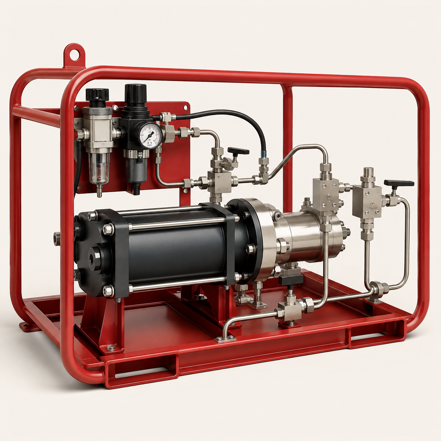
Air-driven liquid pumps convert relatively low-pressure compressed air into higher hydraulic pressure through a differential-piston arrangement. They are compact, controllable pressure sources for upstream work where electrical drive is unavailable or undesirable. The selected pump ratio, displacement, seals and wetted materials must match the required outlet pressure, flow, fluid and duty cycle.
How it works
Drive air reciprocates a large-area air piston connected to a smaller hydraulic plunger. Inlet and outlet check valves direct liquid through the hydraulic section. The pump cycles rapidly while filling, slows as outlet resistance rises, and stalls when forces reach equilibrium. If downstream pressure falls, or drive pressure is increased, cycling restarts automatically. Actual outlet pressure and flow depend on friction, back pressure, drive-air condition and the selected pump.
Available configurations
- Compact low-power pump for intermittent testing and actuation
- Single-air-head pump for general pressurisation duty
- Double-air-head or staged arrangement for higher outlet pressure
- Double-acting hydraulic section for increased flow
- Pump package with reservoir, controls, gauge and isolation valves
Main components
- Air-drive piston and cylinder
- Pilot-operated cycling valve
- Hydraulic plunger or piston
- Inlet and outlet check valves
- Fluid-compatible dynamic seals
- Distance piece or vented separation where required
- Air filter, regulator, gauge and speed control
- Reservoir, suction strainer and pressure-side accessories
Typical upstream applications
- Hydrostatic and liquid leak testing
- Well equalisation using an approved compatible liquid
- Chemical, methanol, glycol or grease injection where materials and seals are suitable
- Wellhead and valve hydraulic actuation
- Packer inflation and hydraulic-tool operation
- Relief-valve liquid testing and setting