
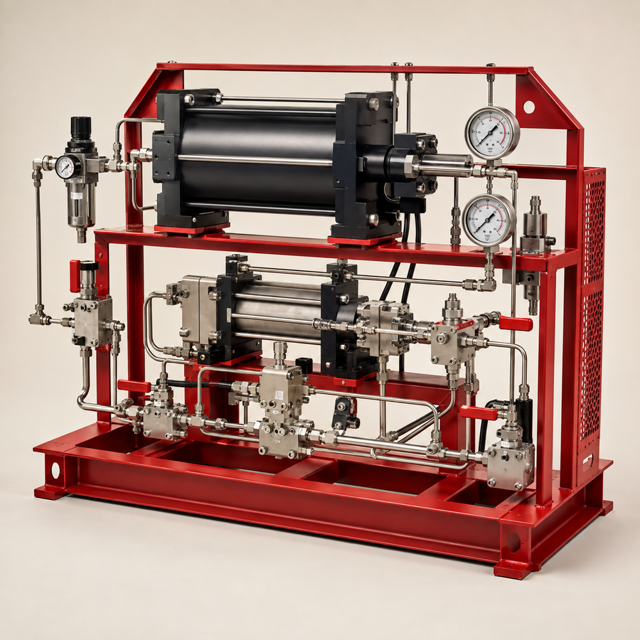
TECHNICAL OVERVIEW
Purpose and operating principle
Gas booster systems use a larger-area drive piston to reciprocate one or more gas pistons, increasing gas pressure for transfer, charging or process support. The selected configuration must reflect suction pressure, required discharge pressure, gas composition, flow, temperature rise, duty cycle, cleanliness and oxygen-service limitations where applicable.
How it works
Compressed air drives the booster section while inlet and outlet check valves control process-gas flow. The booster cycles while the available drive force exceeds the opposing process-gas force and stalls near pressure balance. Multi-stage arrangements divide the compression ratio and may be selected where a single stage would create excessive ratio or discharge temperature. Actual performance depends strongly on suction pressure and available drive-air flow.
Available configurations
- Single-acting single-stage booster
- Double-acting single-stage booster
- Two-stage booster
- Multi-booster package for flow or redundancy
- Skid with receiver, filtration, cooling and controls
Main components
- Pneumatic drive section and cycling valve
- Single or multiple gas sections
- Gas inlet and outlet check valves
- Interstage piping and cooling where required
- Air controls, isolation valves and gauges
- Gas filters, separators and relief devices
- Process-pressure instruments and shutdowns
- Frame, guards and packaged tubing
Typical upstream applications
- Nitrogen accumulator and pulsation-dampener charging
- Compatible-gas transfer and cylinder charging
- Gas recovery and pressure intensification
- Relief-valve gas testing under an approved procedure
- Dry-gas-seal and barrier-gas support
- Emergency air-receiver charging