
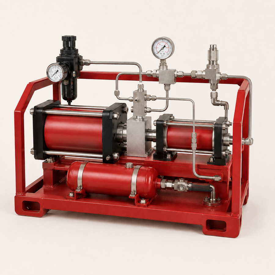
TECHNICAL OVERVIEW
Purpose and operating principle
An air-pressure amplifier uses compressed air as both the drive medium and the process gas to generate a higher local air pressure. It is suited to intermittent or moderate-flow duties where the existing plant-air pressure is below the receiving or actuator requirement. Amplifier selection is based on inlet pressure, required outlet pressure, consumption, receiver volume and recharge time.
How it works
Drive air acts on a larger-area piston connected to one or more compression pistons. Check valves draw in and discharge the process air as the assembly reciprocates. The amplifier slows as outlet pressure rises and stalls near its force-balance condition, then restarts when downstream demand lowers pressure. A receiver can smooth pulsation and provide short-duration peak flow.
Available configurations
- Single-acting single-stage amplifier
- Double-acting single-stage amplifier
- Two-stage amplifier for higher pressure ratio
- Amplifier with air receiver
- Duplex packaged system for capacity or standby
Main components
- Drive piston and cycling valve
- Air compression piston or pistons
- Inlet and discharge check valves
- Air filter and moisture separation
- Pressure regulators, gauges and isolation valves
- Receiver and safety relief valve where required
- Automatic controls and low/high-pressure switches
- Frame, guards and silencing
Typical upstream applications
- Local plant-air pressure amplification
- Pneumatic valve and actuator supply
- Emergency engine-start receiver charging
- Fire-pump or generator starting-air support
- Pneumatic pressure testing only where an approved risk-controlled procedure permits it
- Higher-pressure instrument-air duty where approved