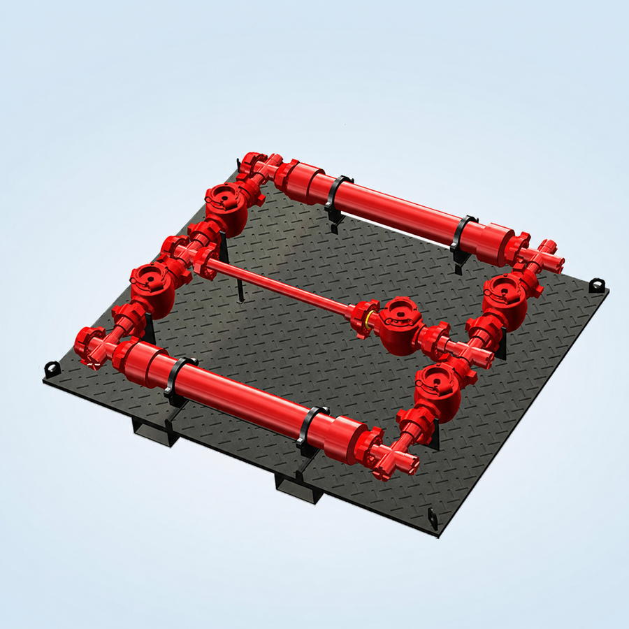
A debris catcher manifold, also called a trash catcher, removes larger debris from returning well fluids during flowback, well clean-up and surface testing. Capturing solids upstream reduces the risk of damage to choke valves, sand probes, meters and other sensitive downstream equipment.
How the arrangement works
A typical arrangement provides two debris-capture paths and one bypass path. Flow is directed through a selected screen chamber while the alternate chamber is available for isolation, safe depressurisation and screen cleaning or replacement. Quick-union access and a dedicated pressure-relief/discharge arrangement support safer screen servicing. Operating sequences must follow the approved line-up and depressurisation procedure.
Technical features
Three flow paths: two debris-capture channels and one bypass channel
Double removable fishing/filter screens
Five-valve and nine-valve reference arrangements
Low-torque plug-valve, ULT plug-valve or slab-gate-valve options
Quick-union screen-chamber access
Dedicated discharge/pressure-relief provision before screen removal
Replaceable screens selected for the expected debris size
Skid-mounted arrangement for flowback, clean-up and well-testing layouts
Typical applications
Flowback and well clean-up
Surface well testing
Wellstream sand and proppant removal
Coiled-tubing clean-up
Underbalanced-drilling returns
Protection of downstream chokes and measurement equipment
TECHNICAL DATA
Selection and supply basis
Reference nominal sizes
2-1/16 in, 2-9/16 in, 3-1/16 in and 4-1/16 in
Reference working-pressure range
5,000 to 15,000 psi
Product specification levels
PSL 1, PSL 2, PSL 3 and PSL 3G where required and confirmed
Reference material classes
AA, BB, CC, DD, EE, FF and HH; final class selected for service
Reference temperature range
API 6A classes K through U (-60 °C to 121 °C)
Design basis
API Spec 6A where applicable to the selected pressure-containing components
Reference screen openings
3, 4, 5, 6 or 8 mm
Reference single-screen volume
6 to 22 L
Reference package arrangements
3 ft body; 5-valve or 9-valve configurations, subject to approved layout
Service selection
Standard or sour service; metallurgy, hardness, seals and trim confirmed against the approved fluid composition
Inspection and testing
Material traceability, dimensional inspection, NDE and pressure/functional testing according to the approved ITP
Documentation
Datasheet, drawings, MTRs, NDE reports, pressure-test records and operating information as specified
Supply positioning
Energy Equipment International supplies surface well-testing equipment against approved project requirements. Manufacturing, monogram, certification and performance claims apply only when confirmed in the selected supplier’s approved documentation.