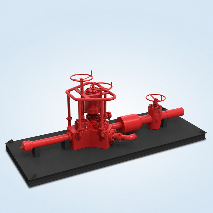
A flowhead, also called a surface test tree, is a pressure-control assembly installed at the top of a test string. Its principal duty is to control flow into and out of the well while providing flow- and kill-line access, a swab access point and a safe handling interface.
How the arrangement works
The typical arrangement uses a master valve, swab valve and two wing valves. One wing can be hydraulically actuated for remote closure. A lifting sub and quick-union connection provide an upper handling and pressure-access interface, while an optional swivel below the main body allows the string to rotate without rotating the connected surface lines. The master valve may be integral to the main block or positioned below it.
Technical features
Solid-block surface control head for well testing, perforating and wireline duties
Master valve, swab valve, flow-wing valve and kill-wing valve arrangement
Integral-master-valve or below-block master-valve configurations
Manual, pneumatic, hydraulic, fail-safe or electric actuation options according to the approved design
Optional oil- or grease-filled swivel below the central body
Top handling sub compatible with the selected elevator arrangement
ACME-threaded or flanged main-bore connection options
Downward-angled flow and kill outlets available where rig-up space is restricted
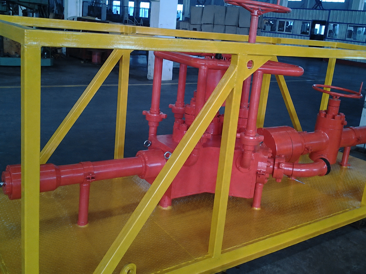
Removable crash frame available to protect valves and actuators
Metal-to-metal sealing and hard-faced slab-gate trim available for severe service
Typical applications
Onshore and offshore well testing
Drill-stem testing and reservoir clean-up
Wireline and perforating operations
Slickline and coiled-tubing intervention
Well stimulation
Completion and subsea installation support, subject to the approved programme
TECHNICAL DATA
Selection and supply basis
Reference nominal sizes
3-1/16 in to 5-1/8 in
Reference working-pressure range
3,000 to 15,000 psi
Product specification levels
PSL 1, PSL 2, PSL 3 and PSL 3G where required and confirmed
Reference material basis
Standard service through high-H₂S/high-CO₂ duties, including DD through HH-NL selections
Reference temperature range
API 6A classes K through U (-60 °C to 121 °C)
Actuation options
Manual, pneumatic, double-acting hydraulic, fail-safe hydraulic or electric
Design basis
API Spec 6A where applicable to the selected assembly
Main-bore connections
ACME threaded or flanged; final interface by approved string and surface-layout details
Overlay
Corrosion-resistant overlay available according to project requirements
Service selection
Standard or sour service; metallurgy, hardness, seals and trim confirmed against the approved fluid composition
Inspection and testing
Material traceability, dimensional inspection, NDE and pressure/functional testing according to the approved ITP
Documentation
Datasheet, drawings, MTRs, NDE reports, pressure-test records and operating information as specified
Supply positioning
Energy Equipment International supplies surface well-testing equipment against approved project requirements. Manufacturing, monogram, certification and performance claims apply only when confirmed in the selected supplier’s approved documentation.
REFERENCE IMAGES
Equipment and component details
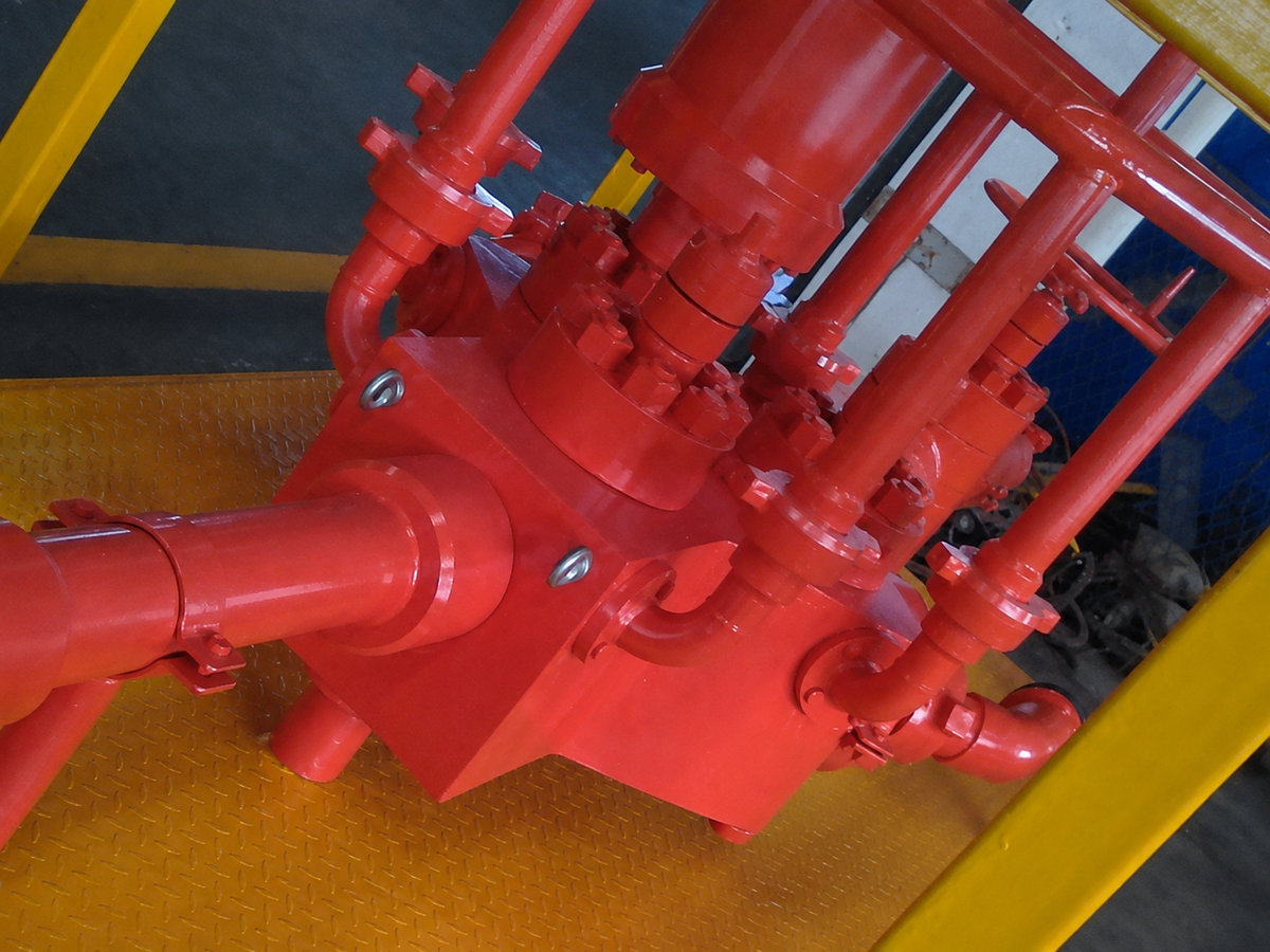
Flowhead assembly and protected valve arrangementFlowhead block, valves and connection detail