PRODUCT OVERVIEW
Purpose and system role
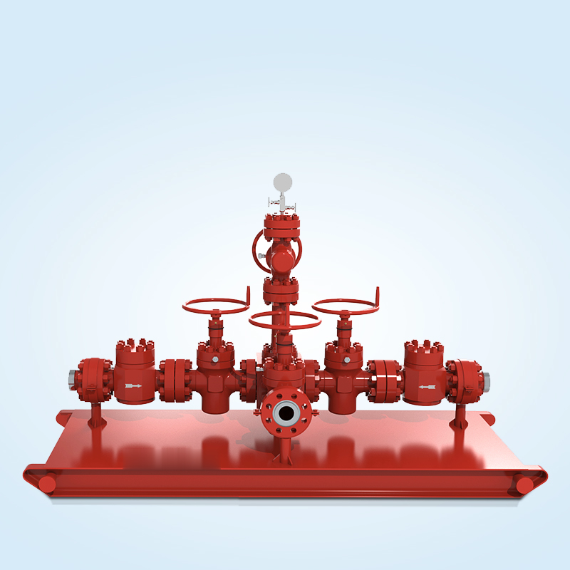
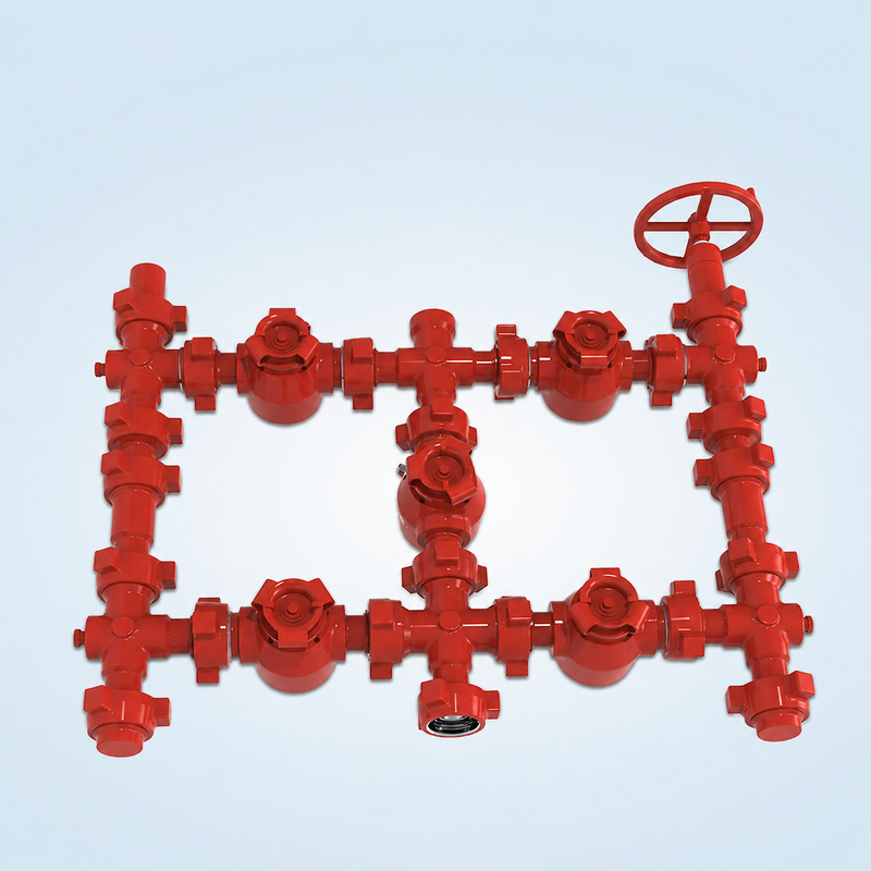
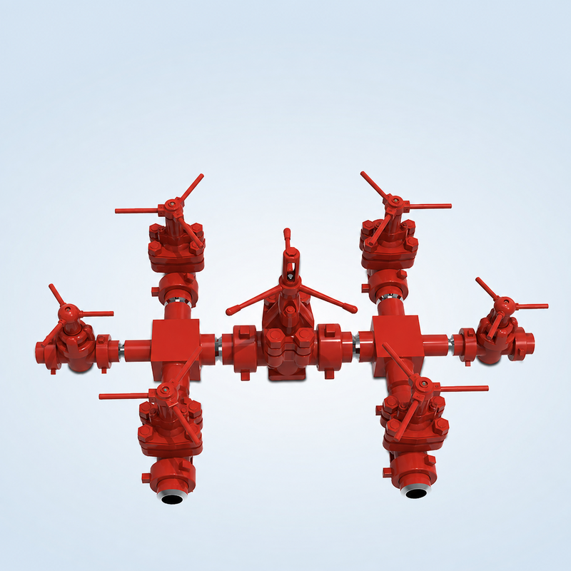
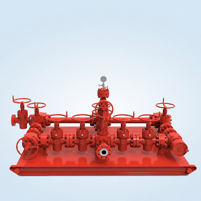
A choke manifold combines isolation valves, drilling chokes, blocks, spools, instrumentation and an outlet header or buffer chamber. When the BOP is closed, it provides a controlled route for well returns and enables the operator to manage casing pressure while circulating an influx or carrying out controlled clean-up.
Functions
- Diverts returns away from the normal flowline after BOP closure
- Controls backpressure during kick circulation
- Provides selectable flow paths through fixed, manual-adjustable or hydraulic chokes
- Supports well clean-up, blow-off and surface well-test duties where specified
- Provides isolation so a choke or flow path can be serviced while an alternate path remains available
- Accommodates local or remote pressure monitoring and choke control
Available configurations
- Single-wing, dual-wing or multi-wing layouts
- Single or dual isolation-valve arrangements
- Manual adjustable, positive and hydraulic drilling chokes
- Flanged or studded blocks, spools and outlet connections
- Local operation or remote hydraulic console
- Conventional horizontal skid or project-specific compact arrangement
- One-piece or split skid for transport and rig-site assembly
Principal components
- API gate valves and drilling choke valves
- Studded blocks, crosses, tees and spacer spools
- Pressure gauges, transmitters and instrument take-offs
- Buffer chamber or multi-outlet header
- Blind flanges with fluid-cushion arrangements where specified
- Skid, lifting points and transport supports
Typical applications
- Drilling well-control circulation
- Kick-pressure management
- Well clean-up and controlled blow-off
- Surface well testing and flow-rate evaluation
- High-pressure or sour-service well operations